Pan, Oil: Installation
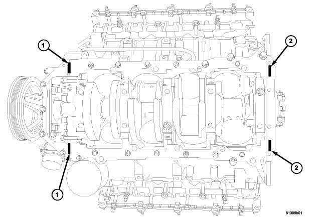
| 1 - Front Cover T-Joints |
| 2 - Rear Oil Retainer T-Joints |
Mopar® Engine RTV must be applied to the 4 T-joints (1, 2), the area where the front cover, rear retainer and oil pan gasket meet. The bead of RTV should cover the bottom of the gasket. This area is approximately 4.5 mm x 25 mm in each of the 4 T-joint (1, 2) locations.
- Clean the oil pan gasket mating surface of the engine block and oil pan.
- Apply Mopar® Engine RTV at the 4 T-joints (1, 2).NOTE:
When the oil pan is removed a NEW oil pan gasket and the integral windage tray assembly must be installed, the old gasket cannot be reused.
- Install a NEW oil pan gasket/windage tray.
- Using a NEW
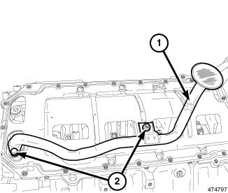
O-ring, Install the oil pump pickup tube (1). Tighten bolt and nut (2) to the proper specification. Refer to TORQUE SPECIFICATIONS
.
NOTE:
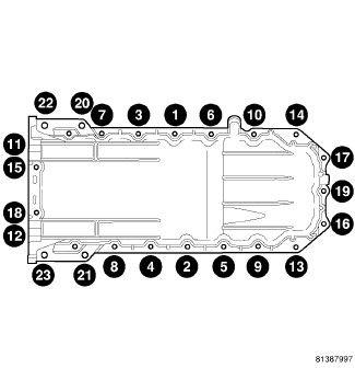
The horizontal M10 bolts (11, 12, 15, 18) are 5 mm longer in length then the vertical M10 bolts (20, 21, 22, 23) and must be reinstalled in their original locations.
NOTE:NEW M6 bolts must be used when reinstalling the oil pan. Do not reuse the old M6 bolts.
- Align the rear of the oil pan with the rear face of the engine block and install the NEW M6 and M10 bolts finger tight.
- Using the sequence shown, tighten the M6 retaining bolts to 5 N.m (44 in. lbs.).
- Using the sequence shown, tighten the M10 retaining bolts to 54 N.m (40 ft. lbs.).
- Using the sequence shown, tighten the M6 retaining bolts to 12 N.m (106 in. lbs.).
- Remove support and lower the vehicle.
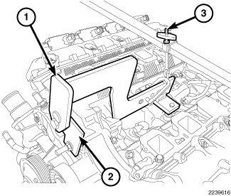
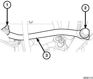
- Using the Engine Lift Fixture (special tool #8984B, Fixture, Engine Lifting) (1), Engine Lift Adapter (special tool #8984-UPD, Adapter, Engine Lift) (2) and the Engine Support Fixture (special tool #8534C, Fixture, Driveline Support) (3) lower the engine into position and remove.
- Install the engine oil dipstick tube and dipstick.
- Raise and support the vehicle.NOTE:
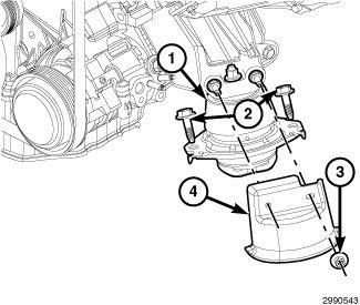
Left side shown, right side similar.
- Install both engine mount lower retaining bolts (2) and tighten to the proper specification. Refer to TORQUE SPECIFICATIONS .
- Install both engine mount heat shields (4). Tighten nuts (3) to the proper specification. Refer to TORQUE SPECIFICATIONS
.
- Install the generator support bracket (3). Tighten fasteners (1, 2) to the proper specification. Refer to TORQUE SPECIFICATIONS
.
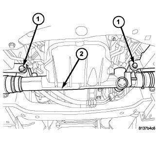
- Position the steering gear (2), install mounting bolts (1) and tighten to the proper specification. Refer to TORQUE SPECIFICATIONS .
- Lightly lubricate the oil filter gasket with clean engine oil.NOTE:
Do not over tighten the oil filter.
Install the oil filter. Refer to FILTER, ENGINE OIL, INSTALLATION .
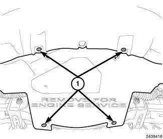
- Install the belly pan and securely tighten bolts (1).
- Remove support and lower the vehicle.
- Install the Variable Valve Timing Solenoid (2). Refer to SOLENOID, VARIABLE VALVE TIMING (VVTS), EXHAUST, INSTALLATION .
- Fill the crankcase with the specified type of engine oil. Refer to CAPACITIES AND RECOMMENDED FLUIDS, SPECIFICATIONS .
- Connect the negative battery cable.
- Start engine and check for leaks.