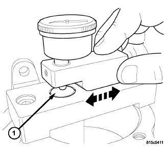
Pinion Depth Measurement
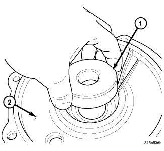
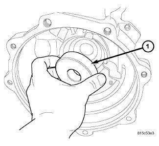
- Install arbor disc (special tool #9681-4, Disc, Arbor) (1) into differential cover (2).
- Install arbor disc (special tool #9681-5, Disc, Arbor) (1) into differential case.
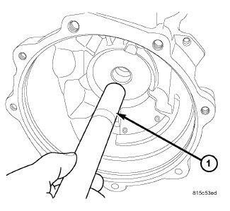
- Install arbor bar (special tool #D-115-3, Arbor) (1) into arbor disc (special tool #9681-5, Disc, Arbor).
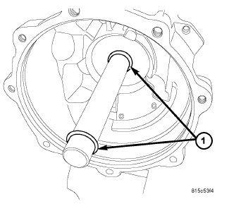
- Install O-rings (1) on arbor bar (special tool #D-115-3, Arbor).
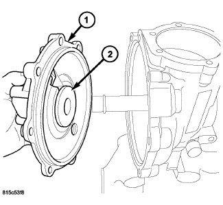
- Install cover (1) to housing.
- Install the cover-to-housing bolts and tighten to the proper torque specifications. Refer to TORQUE SPECIFICATIONS .NOTE:
Make sure gauge plate surfaces are clean to insure an accurate reading
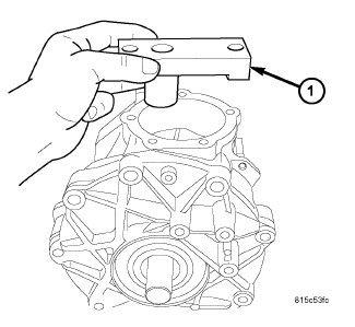
- Install gauge plate (special tool #9681-2, Plate, Gage) (1) to pinion opening.
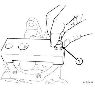
- Install plate-to-housing bolts (1).
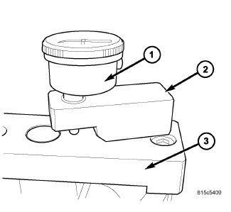
- Install Scooter Block (2) and dial Indicator (1) on gauge plate (special tool #9681-2, Plate, Gage) (3).
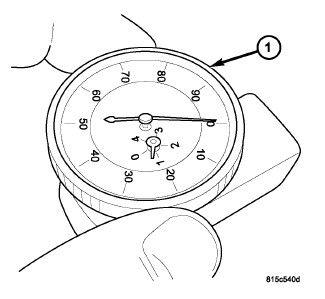
- Zero dial indicator (1).
- Take reading (1) with the dial indicator, measure gage rod protrusion.
- Record gage rod protrusion reading on the dial indicator. The dial indicator reading represents the amount that this particular assembly deviates from the design height.