Theory Of Operation
A vehicle can be equipped with a Single Fan or Dual Fan system. The Single Fan system has two modes of operation (low and high) while the Dual Fan system has three modes of operation (low/medium/high). While the two systems vary in operation of the fans, the configuration of the relays and control circuits are the same for both systems. The Radiator Fan system uses three relays to control the Radiator Fan operation. The Powertrain Control Module (PCM) controls the operation of the relays through two Low Sided Driver (LSD) circuits. The PCM performs diagnostics on the two control circuits.
- The relays are controlled by the PCM as follows:
- Radiator Fan Relay 1 is controlled using the Low Speed Rad Fan Control circuit.
- Radiator Fan Relay 2 and Radiator Fan Relay 3 are controlled simultaneously using the Rad Fan Relay Control circuit.
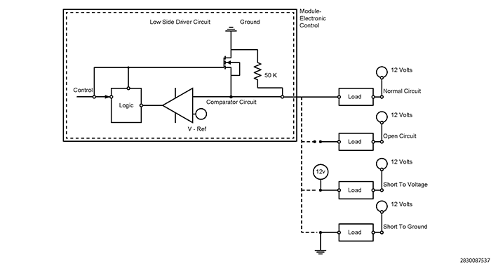
Typical Low Side Driver Operation and Fault Detection: This type of driver circuit is generally used for relay control, controlling a solenoid or a similar type of driver device. The PCM provides a ground to operate the device when switched on. The PCM also provides fault detection for the device, wiring and internal driver. For diagnostic purposes the PCM uses an internal pull down diagnostic resistor connected in series and a voltage reference (V-Ref) comparator for fault detection:
- Circuit Open and Circuit Low Detection: The PCM monitors for an open circuit and short to ground when the driver is switched off. When switched off, the available voltage passes through the device and the internal pull down resistor connected in series. The voltage at the comparator circuit should be close to Battery voltage since the majority of the voltage drop occurs through the diagnostic resistor. If the available voltage is less than the V-Ref, a fault is set. In this case the V-Ref would be slightly below Battery voltage.
- Circuit High Detection: The PCM monitors for a short to voltage when the driver is switched on. When the driver is switched on providing a path to ground through the transistor, the available voltage should be pulled low near zero volts since the comparator circuit is monitoring the ground side of the device. If the voltage is greater than the V-Ref, a fault is detected. In this case V-Ref would be slightly above zero volts.
A load that has a resistance that is below manufacturer specification, or a second load device shorted to the low side driver circuit can cause excessive current draw on the internal driver. The driver will be switched off to protect against overheating and damaging the driver. In this instance the Circuit High fault may be detected because the available voltage on the comparator circuit is above V-Ref.
Single Fan System Control
- Low Speed Operation: The Low Speed Rad Fan Control circuit is grounded energizing Radiator Fan Relay 1 (High/Low). The Battery voltage output from the relay passes through a resistor on the back of the Radiator Fan connector reducing the voltage to the fan motor for low speed operation.
- High Speed Operation:
The Rad Fan Relay Control circuit is grounded energizing Radiator Fan Relay 2 (Series/Parallel) and Radiator Fan Relay 3 (Med/High). The Battery voltage output from Radiator Fan Relay 3 goes directly to the fan motor bypassing the resistor on the back of the Radiator Fan connector.NOTE:
On the Single Fan system Radiator Fan Relay 2 has no effect on the function of the system since this system does not have two fans that operate in series. However the relay must be present and functional for diagnostic purposed in the PCM. A faulty relay or circuitry to the relay will cause the PCM to set the DTC (P0481).
Dual Fan System Control
- Low Speed Operation: The Low Speed Rad Fan Control circuit is grounded energizing Radiator Fan Relay 1 (High/Low). The Battery voltage output from the relay passes through one fan motor back through the off terminal in Radiator Fan Relay 2 (Series/Parallel), through the off terminal of Radiator Fan Relay 3 (Med/High), through the second fan motor and then to ground. The fans are operated in series which reduces the voltage to both fan motors for low speed system operation.
- Medium Speed Operation: Radiator Fan Relay 1 (High/Low) is de-energized and the Rad Fan Relay Control circuit is grounded energizing Radiator Fan Relay 2 (Series/Parallel) and Radiator Fan Relay 3 (Med/High). The Battery voltage output from Radiator Fan Relay 3 (Med/High) goes directly through one fan motor and then to ground. The other fan motor is connected to ground through Radiator Fan Relay 2 (Series/Parallel), however the fan motor does not operate because no voltage is being supplied from Radiator Fan Relay 1 (High/Low). One fan motor operates at high speed for medium speed system operation.
- High Speed Operation: Both control circuits are grounded energizing all three relays. The Battery voltage output from Radiator Fan Relay 1 (High/Low) passes through one fan motor back through Radiator Fan Relay 2 (Series/Parallel) to ground. The Battery voltage output from Radiator Fan Relay 3 (Med/High) goes directly through the other fan motor and then to ground. Both fan motors operate at high speed for High speed system operation.