Cylinder Head: Removal: Left
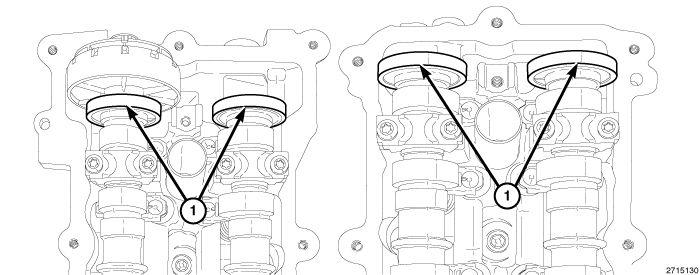
The magnetic timing wheels (1) must not come in contact with magnets (pickup tools, trays, etc.) or any other strong magnetic field. This will destroy the timing wheels ability to correctly relay camshaft position to the camshaft position sensor.
- Perform the fuel pressure release procedure. Refer to FUEL DELIVERY, GAS, STANDARD PROCEDURE .
- Disconnect and isolate the negative battery cable.
- Remove the air cleaner body. Refer to BODY, AIR CLEANER
.
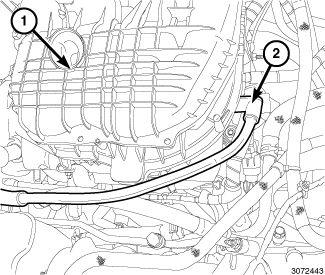
- Remove the fresh air makeup hose (2) from the rear of the intake manifold (1).
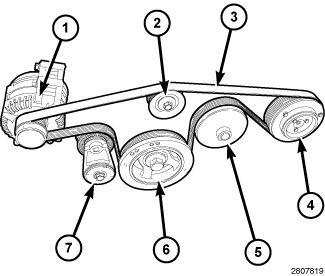
- Rotate the accessory drive belt tensioner (7) counterclockwise until it contacts the stop and remove the accessory drive belt (3), then slowly rotate the tensioner into the freearm position.
- Raise and support the vehicle. Refer to HOISTING, STANDARD PROCEDURE .
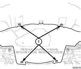
- Remove bolts (1) and the belly pan.
- Drain the cooling system. Refer to STANDARD PROCEDURE .
- Drain the engine oil. Refer to OIL
.
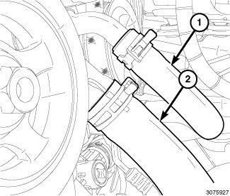
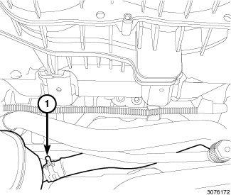
- Remove the lower heater core return hose (1) from the engine coolant pump housing.
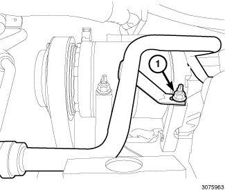
- Remove the heater core return tube lower support bracket retaining nut (1).
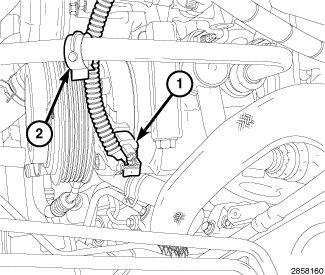
- Disconnect the A/C compressor wire harness connector (1) and disengage the wire harness retainer (2) from the A/C compressor discharge line.
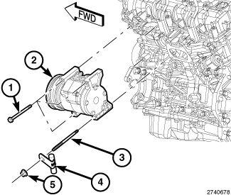
- Remove the A/C compressor lower retaining studs (3).
- Remove support and lower the vehicle.
- Remove the A/C compressor upper retaining bolts (1) and reposition the A/C compressor aside (2).
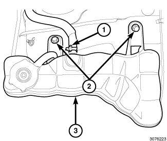
- Remove the coolant bottle return hose (1).
- Remove the heater core purge hose (1) from the coolant bottle.
- Remove bolts (2) the coolant bottle (3).
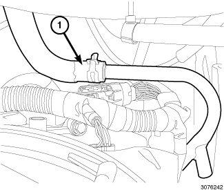
- Disconnect the heater core return hose (1).
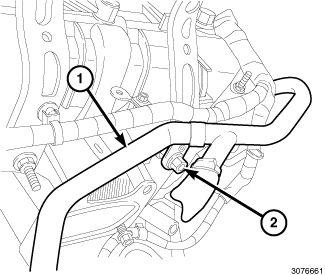
- Remove the heater core return tube upper support bracket retaining nut (2) and remove the tube (1).
- Remove the upper and lower intake manifolds and insulator. Refer to MANIFOLD, INTAKE, REMOVAL .
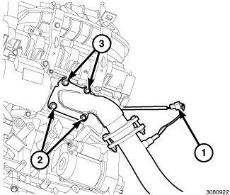
- Disconnect the left upstream oxygen sensor wire harness connector (1).
- Loosen the lower down pipe flange bolts (2).
- Remove the upper down pipe flange bolts (3) and position the down pipe and catalytic converter aside.
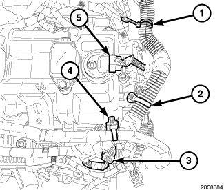
- Disconnect the Engine Coolant Temperature (ECT) sensor wire harness connector (3).
- Disconnect the ignition coil capacitor wire harness connector.
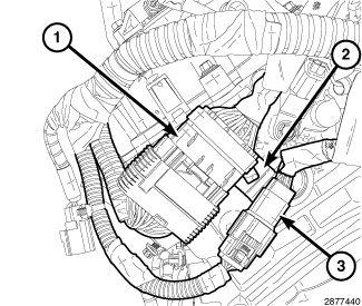
- Disconnect the injection/ignition wire harness connector (1).
- Disconnect the engine oil pressure/temperature sensor wire harness connector (3).
- Unfasten the injection/ignition wire harness and the oil pressure/temperature sensor wire harness from the retainer bracket (2) on the rear of the left cylinder head.
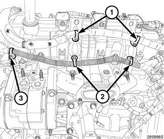
- Unfasten two starter wire harness retainers (1) from the upper intake manifold support brackets.
- Unfasten one main wire harness retainer (3) from the left cylinder head cover and two retainers (2) from the upper intake manifold support brackets.
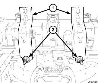
- Remove the bolts (2) and the left upper intake manifold support brackets (1).
- Remove the spark plugs. Refer to SPARK PLUG, REMOVAL .
- Remove the cylinder head covers, lower and upper oil pans, crankshaft vibration damper and engine timing cover. Refer to COVER(S), ENGINE TIMING
.NOTE:
Take this opportunity to measure timing chain wear. Refer to VALVE TIMING, STANDARD PROCEDURE .
CAUTION:When aligning timing marks, always rotate engine by turning the crankshaft. Failure to do so will result in valve or piston damage.
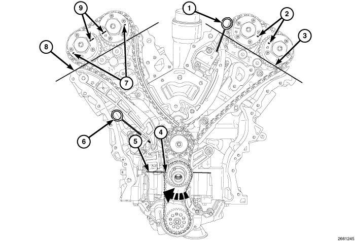
- Rotate the crankshaft clockwise to place the number one piston at TDC on the exhaust stroke by aligning the dimple (4) on the crankshaft with the block/bearing cap junction (5). The left side cam phaser arrows (2) should point toward each other and be parallel to the valve cover sealing surface (3). The right side cam phaser arrows (7) should point away from each other and the scribe lines (9) should be parallel to the valve cover sealing surface (8).CAUTION:
Always reinstall timing chains so that they maintain the same direction of rotation. Inverting a previously run chain on a previously run sprocket will result in excessive wear to both the chain and sprocket.
- Mark the direction of rotation on the timing chain using a paint pen or equivalent to aid in reassembly.CAUTION:
When the timing chains are removed and the cylinder heads are still installed, DO NOT rotate the camshafts or crankshaft without first locating the proper crankshaft position. Failure to do so will result in valve or piston damage.
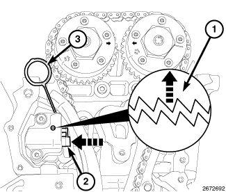
- Reset the left cam chain tensioner by lifting the pawl (1), pushing back the piston (2) and installing Tensioner Pin (special tool #8514, Pins, Tensioner) (3)
Refer to VALVE TIMING, STANDARD PROCEDURE .
NOTE:Minor rotation of a camshaft (a few degrees) may be required to install the camshaft phaser lock.
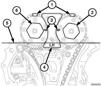
- Install the LH Camshaft Phaser Lock (special tool #10202, Locks, Camshaft/Phaser) (4).
- Loosen both the intake oil control valve (6) and exhaust oil control valve (2).
- Remove the LH Camshaft Phaser Lock (special tool #10202, Locks, Camshaft/Phaser) (4).
- Remove the oil control valve (2) from the left side exhaust cam phaser and pull the phaser off of the camshaft.
- Remove the oil control valve (6) from the left side intake cam phaser and pull the phaser off of the camshaft.
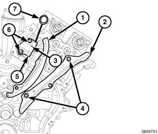
- Remove the left cam chain tensioner arm (1).
- Remove two T30 bolts (6) and the left cam chain tensioner (5).
- Remove two T30 bolts (4) and the left cam chain guide (2).
NOTE:
If the rocker arms are to be reused, identify their positions so that they can be reassembled into their original locations.
- Remove the rocker arms. Refer to ROCKER ARM, VALVE
.NOTE:
If the hydraulic lifters are to be reused, identify their positions so that they can be reassembled into their original locations.
- If required, remove the hydraulic lifters.CAUTION:
DO NOT use an impact gun or any type of power tools to break loose or remove the head bolts. This can cause the threads to pull out of the block with the bolts.
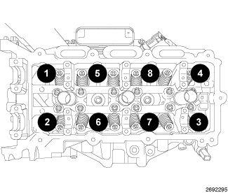
- Using the sequence shown, remove the cylinder head retaining bolts.NOTE:
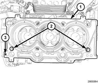
Right head gasket shown, left head gasket similar.
WARNING:The multi-layered steel head gaskets have very sharp edges that could cause personal injury if not handled carefully.
CAUTION:Do not lay the cylinder head on its gasket sealing surface, due to the design of the cylinder head gasket, any distortion to the cylinder head sealing surface may prevent the gasket from properly sealing resulting in leaks.
NOTE:The head gasket (1) crimps the locating dowels (2) and the dowels may pull out of the engine block when the head gasket is removed.
- Remove the cylinder head and gasket (1) and discard the gasket.
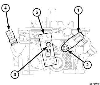
- If required, remove the Engine Coolant Temperature (ECT) sensor (4).
- If required, remove the bolt (2) and the ignition coil capacitor (1).
- If required, remove the bolt (3) and the engine wire harness retainer bracket (5).